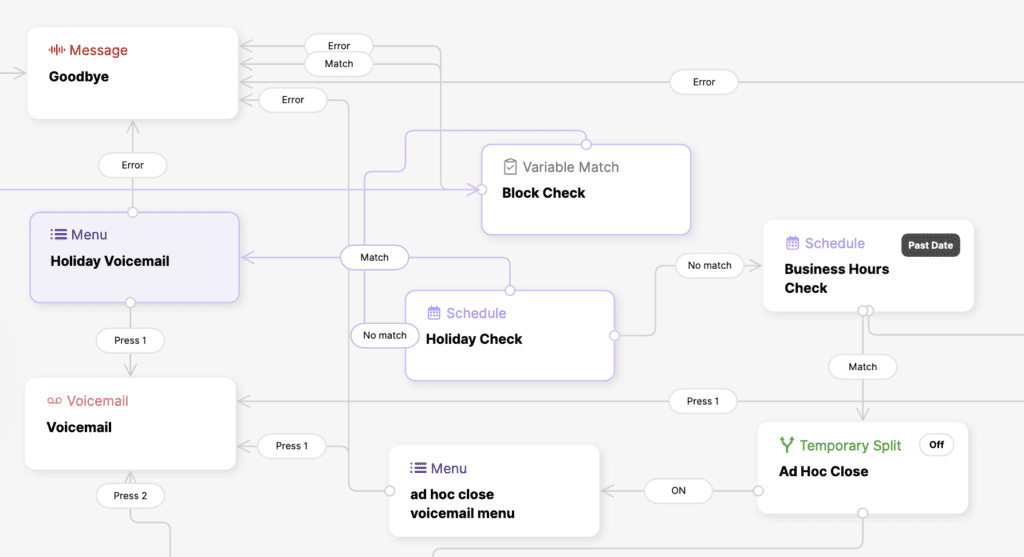
Please get to know the IVR interface and understand its features to make it easy to manage your IVRs. It’s essential that you recognize how to work within the confines of the IVR.
IVR Interface #
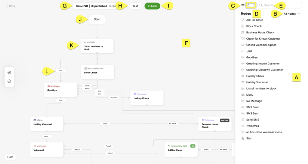
- [A] – List of nodes that are currently used in the IVR
- [B] – Node list filter (Errors, All Nodes)
- Errors – View a list of the nodes (if any) with errors. IVR changes cannot be published if there are errors.
- All Nodes – View all available nodes (default)
- [C] – Menu to return to the node list
- [D] – Back and forward button to see recently viewed nodes
- [E] – Search for nodes by name or type
- [F] – Area the IVR is built
- [G] – IVR status and version list
- [H] – Test the current IVR configuration
- [I] – Publish action to release IVR changes
- [J] – Where the call enters the IVR.
- [K] – Node
- Click on a Node to see more information about how the node is configured. More information is displayed on the right side of the screen.
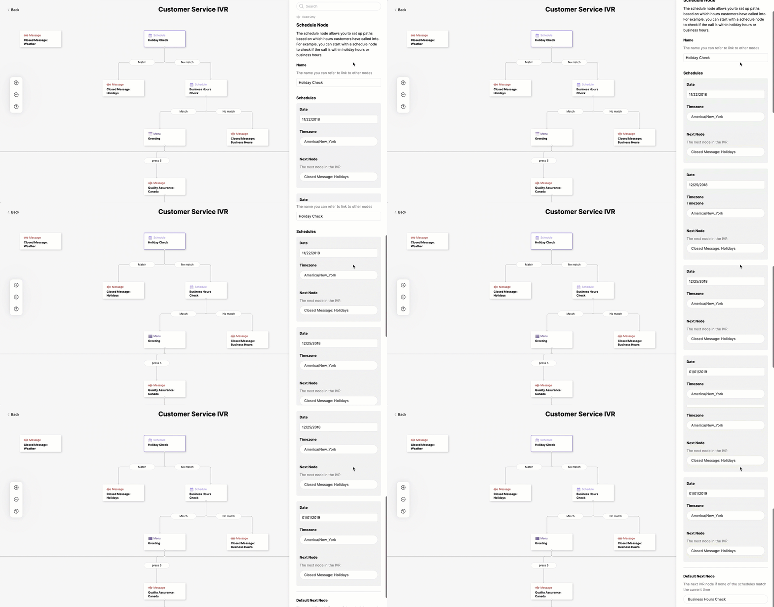
[L] – Match parameters linked to the next node (pill)
- Click on a pill element in the IVR tree to highlight (purple line) the relationship between nodes.
IVR Experience #
Get to know the standard IVR editing experience before you create an IVR.
Drag and Drop
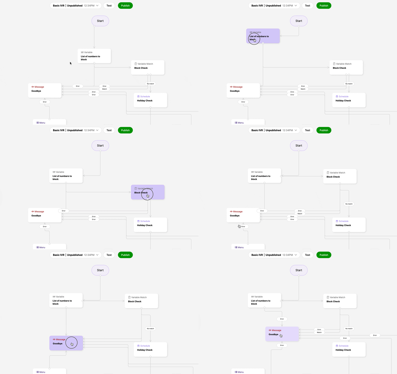
Move nodes around by clicking and holding down the node as you move your mouse. Linked nodes remain linked as the node is moved around.
Pan Around and Zoom In/Out
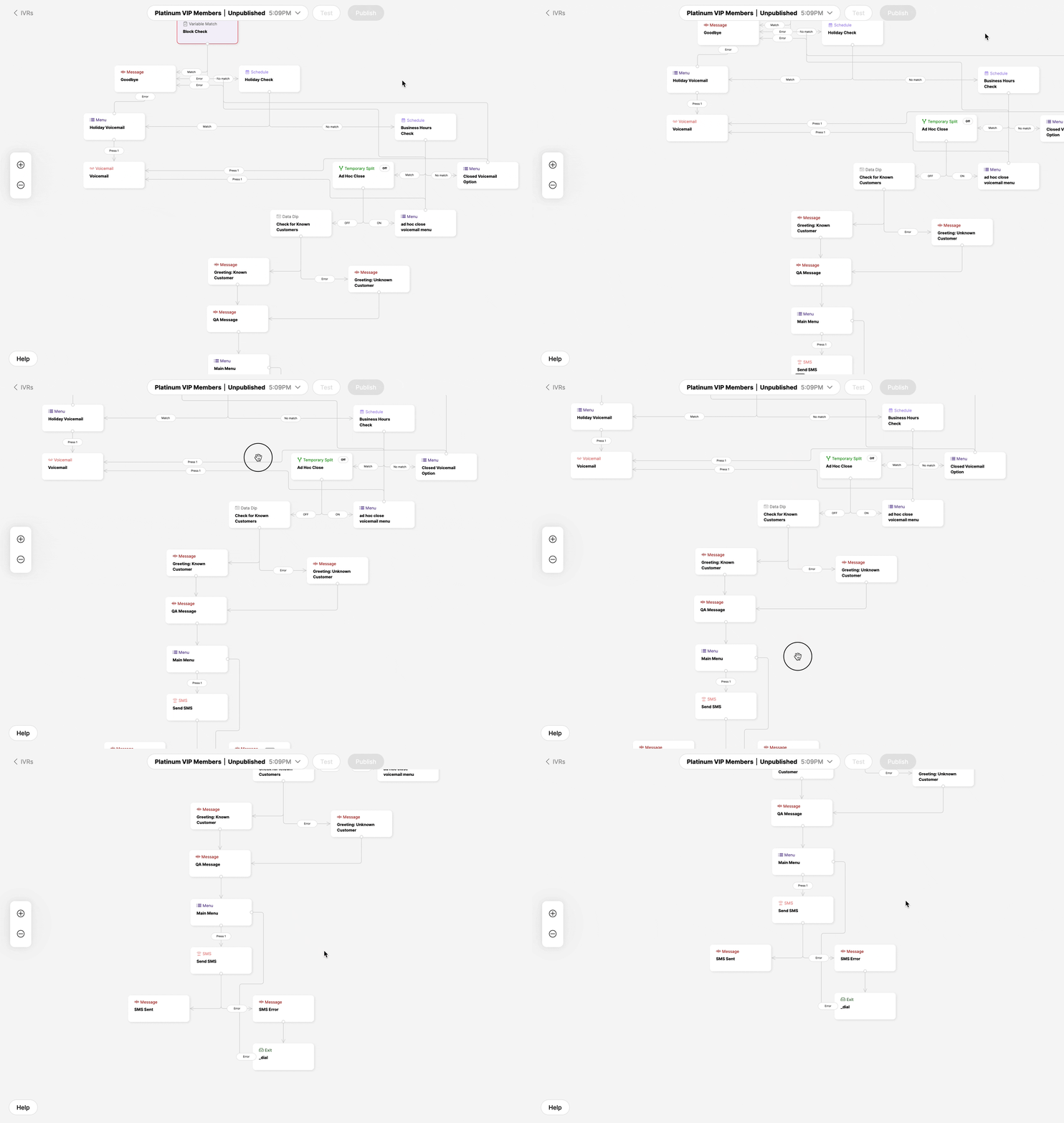
Click outside the node until the hand appears and drag the page to move around. Use the + and – icons to zoom in and out.
Linked IVR nodes
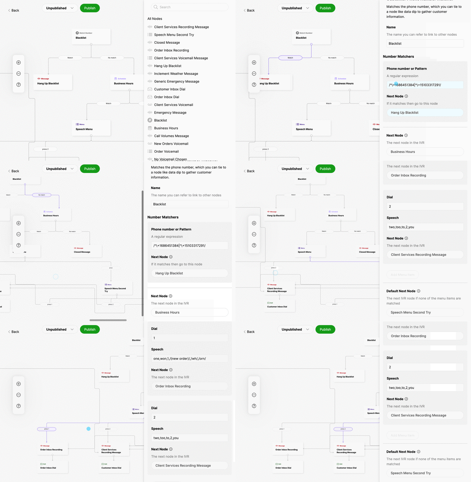
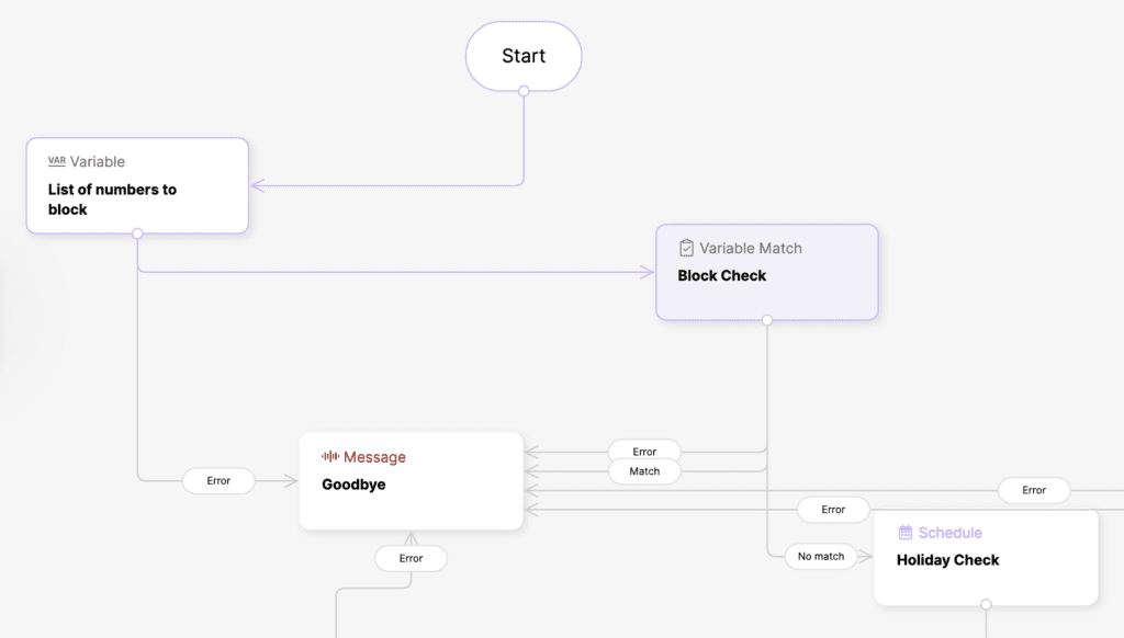
Start signifies where a call enters the IVR. The gray lines indicate how calls are configured to go from one node to the next through the Default Next Node and Error Node settings. Upon clicking a node, follow the purple flow lines to see how calls are sent from one node to the next.
Default Next Node and Error Node Options
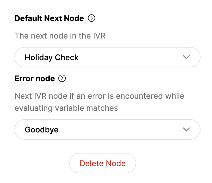
- Default Next Node – Selection of existing nodes that indicate which node a call is passed to from the current node. When set, a gray line appears on the tree to show the connection between the nodes. You can also create a new node from here.
- Error Node – Some node types include an Error Node option. Here, you can choose the node that a call is passed to if an error occurs. You can also create a new node from here. For example, if a Data Dip node cannot verify a Customer, the Error Node should point to a node that allows the caller to continue even if they are unidentified.
Match Parameters (pill shape)
As nodes are linked using the Default Next Node and Error Node option, the match parameters (looks like a pill) indicate how a call is moved to a linked node if a requirement in the node configuration is matched or input is made. Examples include:
- Match
- Error
- Press X (X = DTMF number input)
- On/Off
